All Posts By

Eugene

What is Modbus?

By Blog

Modbus is a data transmission protocol developed by Modicon in 1979 for industrial control applications. It uses a master-slave architecture, where one device is in charge and requests information from multiple (slave) devices. Modbus is a simple command and control protocol that has been adapted to a number of media including TCP/IP, SMS, and wireless transceivers. Modbus is widely used for low-power, industrial controls.

Modbus is an active standard and is documented by the Modbus Organization. Wikipedia also has a brief article on Modbus.

RS‑485 uses a balanced electrical signal. It is very tolerant of electrical noise, Ethernet and USB use similar signal levels.

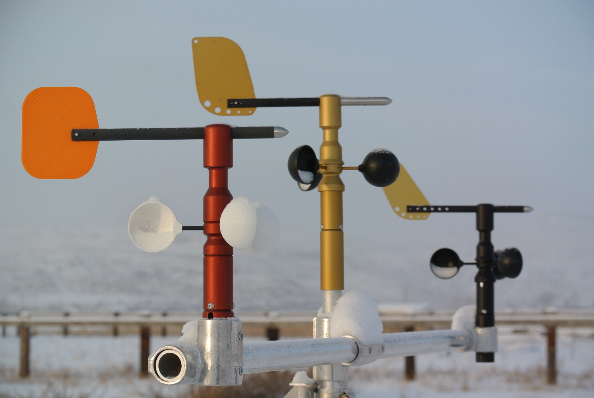
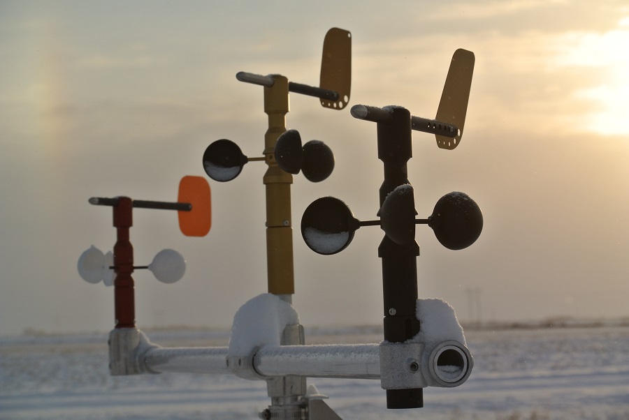
Dyacon air sensors (TPH‑1) and wind sensors (WSD‑1) use Modbus RTU frame over RS‑485 at a default data rate of 19200 kbps. The data rate was selected as a balance between low power and long cable runs, allowing for runs of over 1000 ft. The data rate may be set between 1200 bps and 38400 bps. Cat‑5 cable is a low-cost solution for extending the sensor cables.

Multiple Modbus RS‑485 devices can be connected to a single data bus. Each Modbus slave device has a unique address. The master sends a “read” request to a specific device address. The slave device responds with the requested data. TPH‑1 and WSD‑1 sensors are Modbus slave devices and must be connected to a master.  Dyacon user manuals contain the necessary information for programming the master device.

The address, data rate, and calibration settings on Dyacon Modbus sensors can be configured through Modbus commands. No special programming software is required.

So what can the sensors connect to?

Dyacon Control Modules
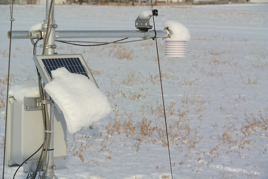
Dyacon control modules (CM‑1 and CM‑2) include ports for WSD‑1 and TPH‑1 Modbus sensors. No programming and no configuration are required. The control modules are the basis for the Dyacon MS‑100 series weather stations.

PC Utility
One of the programs Dyacon uses is Modbus Reader from KurySoft. The companion program Modbus Constructor builds an interface for the sensor. The reader program can then be used license-free on any computer. The reader can send and receive messages for configuring and testing the sensor. Feel free to contact Dyacon if you would like a copy of this construction file for your use.

Modbus Reader also has logging capabilities, but it is not recommended for SCADA or critical data logging functions.

Programmable Logic Controllers (PLCs)
PLCs are industrial automation controllers. These universal controllers are used to control process equipment such as a production line for baking cookies, processing pharmaceuticals, or making circuit boards. They can also be used for automating lighting, pumps, or HVAC environmental controls.

The 24 VDC power input on the Dyacon sensors and control modules allows them to directly connect to PLC controls and power supplies.

Environmental Data Loggers
Data loggers record sensor inputs into local memory for later retrieval and analysis. Many data loggers have multiple analog or digital sensor inputs. Many data loggers will include Modbus RS‑485 host capability.

Please give us a call if we can answer any questions or help you evaluate the best solution for your application.

Eugene

Wind Sensor Development

By Blog

Design and development of the wind sensor WSD‑1 has been an interesting journey. The design was started in January 2013, and the first production run was ordered in January 2014. Several design iterations have been produced. Along the way, several images and videos have been captured.

A few of these have been combined into the following short video presentation:

Eugene

Winter Tripod Setup

By Blog

We spent a few minutes in the snow filming the setup of the tripod. In spite of the ice that froze the warm aluminum components when they were dropped in the snow, the tripod went together smoothly.

The demonstration showed what we expected to be true, which is that the tripod can be fully erected with gloved hands, with the exception of the guy cable clips.

The short and long versions are on the Dyacon YouTube site and the product page.

Stay warm.

Eugene

Frosty Wind Sensors

By Blog

Getting field time for the wind sensors has been a priority from the beginning of the design effort. The following images are a collection of how they fare in some of the cold and snowy conditions.

The first image shows several design variants. The red one was the first design. Drip edges were introduced in the next iteration. The vane fin and anemometer cups were initially 3D printed. A number of cup designs were tested before tooling the injection mold.

Three wind sensor variants.

Three WSD variants on the test mast.

Three WSD variants with snow.

Three WSD variants with snow.

WSD-1 head on w/ snow.

WSD-1 head on w/ snow.

Several cold, dark, and foggy days led to an accumulation of frost. A slight breeze was just enough to turn the cups but not dislodge the ice crystals.

Frosty anemometer and vane are still operational.

Frosty anemometer and vane are still operational.

Snow is always a challenge.

Snow accumulation on solar panel.

Snow accumulation on solar panel.

Snow accumulation melts off a bit.

Snow accumulation melts off a bit.

Snowed in wind sensors did not freeze. The still morning air gave way an hour later, and the cups then turned freely.

Not frozen, just snowed in due to still air.

Not frozen, just snowed in due to still air.

Wind Tunnel Testing

By Blog

With all the time and care we put into their existence, each of our products quickly becomes our “baby.” It’s hard to abuse something so near and dear, but for product designers like me, this type of testing is necessary. We did a couple of rounds of wind tunnel testing on a WSD-1 (the Dyacon wind sensor) using an ELD wind tunnel with an 18″ square test chamber. We tested the sensor up to 60 m/s (134 mph, 215 kph).

Tests were structured around ISO 17713‑1. The tests conducted were:
– Starting threshold
– Transfer function
– Distance constant
– Off-axis response ratio

The ISO 17713‑1 tests were adapted to meet the digital output characteristics of WSD‑1. Additional testing at an independent lab is planned.

The following are some images from the effort:

Wind sensor in tunnel

Wind sensor in wind tunnel test section

A computer is used to capture the raw RS‑485 data during testing. These data will then be used by the firmware to calculate wind speed and direction for the Modbus data frame.

Wind sensor in test section and computer

Computer used to capture RS485 data.

The test section floor and sensor mount allow the sensor to be tilted at 5 degree increments to a maximum incline of 30 degrees forward and back.

Wind sensor off-axis response test

Off-axis response test

How do you abuse a sensitive wind sensor? Mount it to your truck. Rain, snow, dust, salt spray, vibration, gusts, tree branches, and overhead structures have all been encountered. The sensor pictured has racked up more than 5,000 highway miles at road speeds up to 80 mph (128 kph). A sensor like this on your truck is enough to make you the envy of every geek on the road.

Truck with wind sensor mounted

Truck with wind sensor mounted.

Drive safe.

Eugene

Durable Wind Sensor Takes on Garage Doorway

By Blog

Bent Wind Sensor Pole

*NOTE: This blog post is out of date. Some information may no longer be relevant.*

The wind sensor is typically a fixture on my truck. It has traveled thousands of highway miles and drawn a number of curious looks. While some cool jocks have retro 1960s bed exhausts, I have an anemometer. I’m a proud geek.

Exposing the wind sensor to long duration high-speed wind and turbulence, vibration, dust, salt spray, and ice are the kinder treatments. As you can imagine, the elevated position of the wind sensor increases the likelihood that an absent minded driver will try to wipe the thing off on low structures. I’ve done this twice.

The following YouTube post gives the whole story.

Dyacon YouTube Channel

Eugene

Introduction

By Blog

Dyacon, Inc. has turned its experience developing rugged computers into an effort of personal interest to our team: weather instrumentation.

We are pleased to announce the Dyacon product line, which contains weather instruments designed and manufactured in the United States. Dyacon products use sensing elements found in top-of-the line instruments. Direct sales to end users and value-added resellers allow us to keep costs low.

In the wind sensor, you’ll notice a non-contact wind direction sensing element. Most other wind vanes use a potentiometer.

Both wind sensors and air sensors utilize a Modbus data interface for compatibility with programmable logic controllers (PLCs). SDI‑12 is also an option, but it is available only to value-added resellers. The control modules also include a Modbus slave port for connecting a whole weather station to a Modbus host device.

The weather station control modules are highly integrated to improve reliability and value. The single control module circuit board includes all data interfaces, analog ports, logging memory, lightning detector, solar charge controller, LCD, wireless transceiver, and other features. Tight integration enhances power optimization and reduces installation complexity.

We are anxious to hear your input and suggestions. Please drop us a note. Even better, buy something and send us a picture.

Eugene Bodrero & the Dyacon Team

Tripod Announcement

By Announcements, Blog

Tripod Released

Dyacon Tripod-1TM is now available for sale. (No, this isn’t for your camera. . . . But, come to think of it, it could be used for that.)

Tripod-1 is designed to support Dyacon weather station equipment, but it may also be used to support lightweight antenna systems and lighting. The mast height can be raised to as high as 17.4 ft (5.25 m).

Tripod-1 is constructed with machined and welded aluminum. The tripod is available in 7‑ and 10‑leg/mast segment versions. This modular design allows for multiple configurations and facilitates easier field maintenance and repair by the user.

Adjustable legs and large feet ensure stability in a variety of mounting conditions. The feet include holes for 1/2 in stakes and 3/8 in screws.

The tripod is un-anodized to provide better electrical ground and lower cost. Give us a call if you would like an anodized version.

Eugene & the Dyacon Team