Description
Video
Initial Tripod Setup
See more videos.
Description
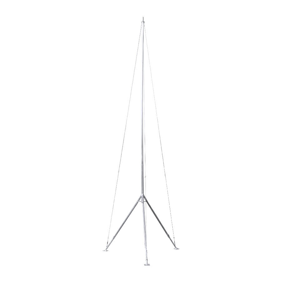
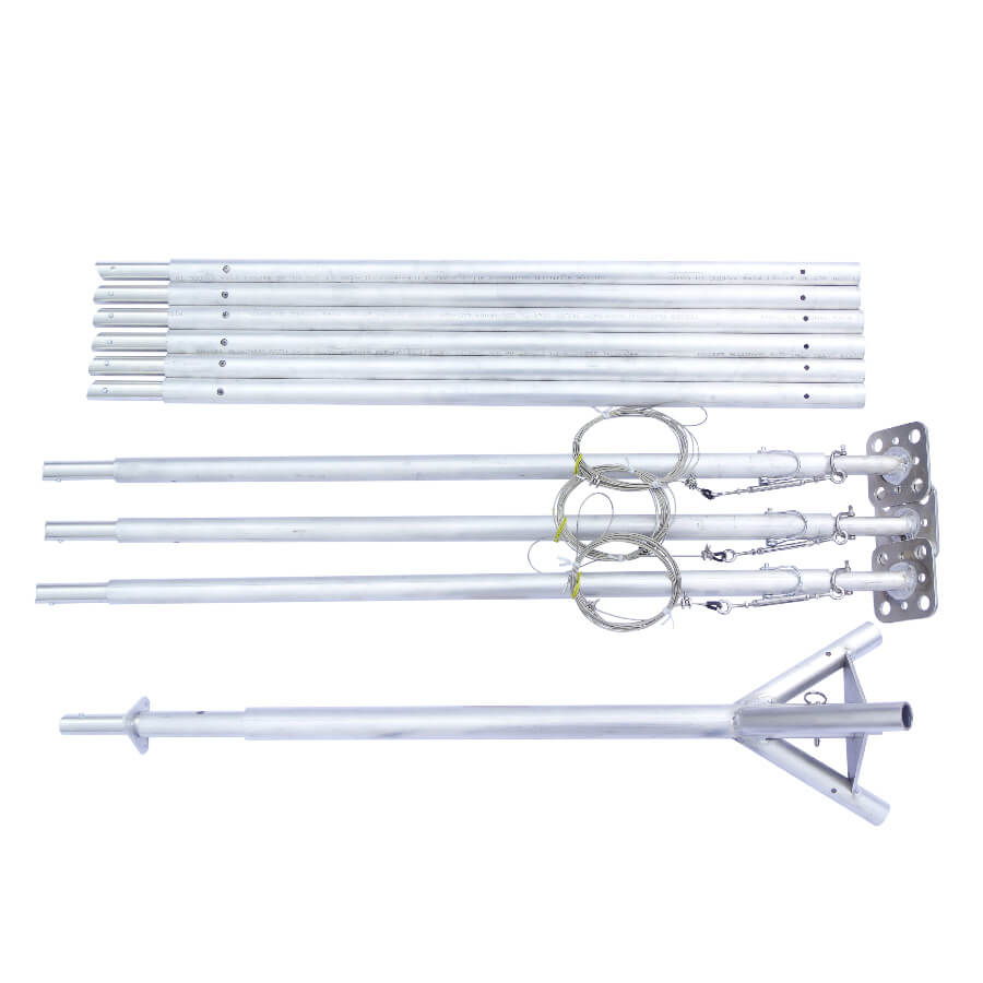
Tripod is a portable, lightweight mounting structure suitable for temporary and permanent equipment installations. It is made of machined and welded 6061 aluminum.
To improve electrical grounding and to minimize cost, Tripod is un-anodized. For use with systems that will be handled frequently, contact Dyacon for anodizing options.
Feature Summary
- Minimal tool assembly
- Field serviceable
- Adjustable leg extensions (up to 13% slope)
- Modular construction
- Versatile configuration
Key Features
Construction
Tripod is made of 6061 machined and welded aluminum. The mast is constructed of 1” (1.32”/33.5 mm) pipe, which is compatible with standard structural pipe fittings.
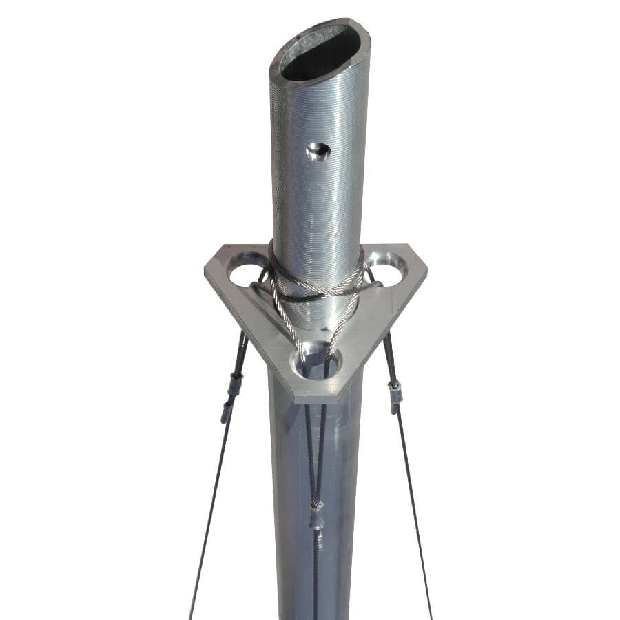
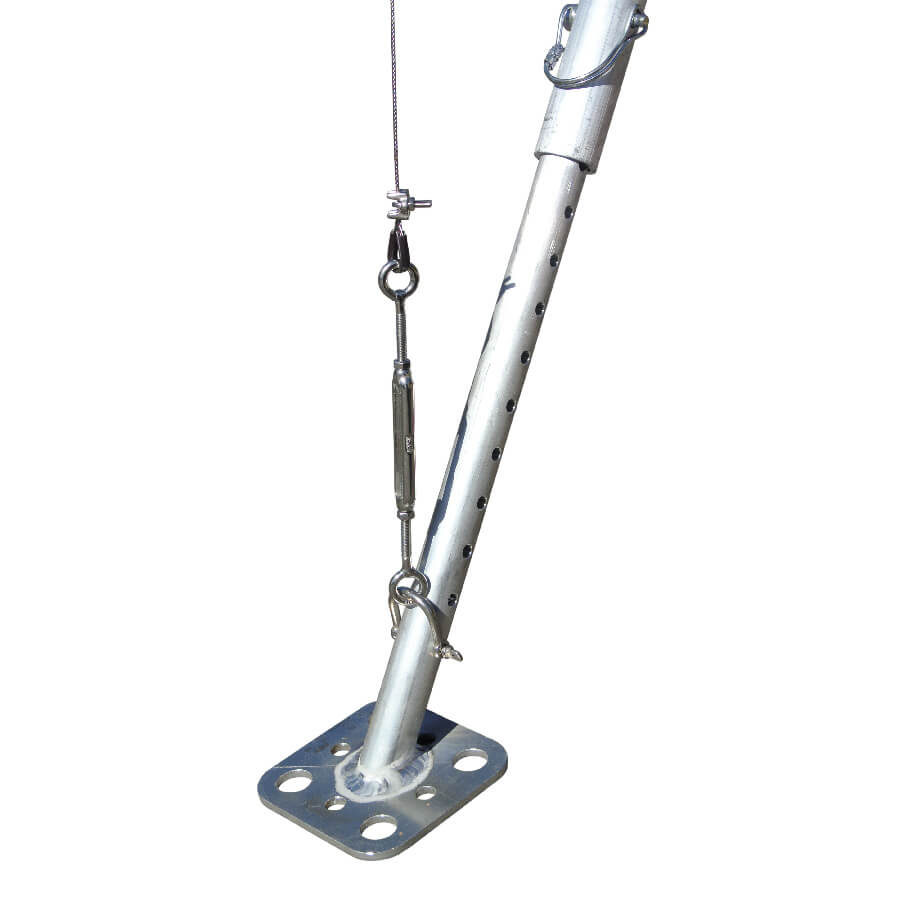
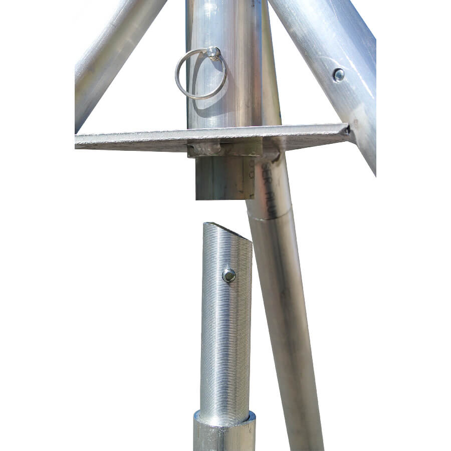
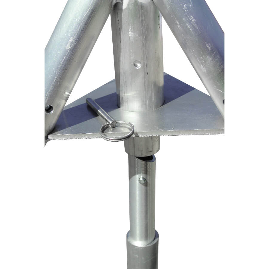
Spring buttons lock each segment, and a quick-release pin secures the mast in the elevated position (as pictured).
Standard wire rope clips are used for the stainless steel wire rope guy lines. Guy lines are typically attached to the legs, but may be attached to stakes or other structures.
316 stainless steel D-shackles and turnbuckles make guy line tensioning fast and secure.
Assembly Tools
A 7/32 inch (5.5 mm) open-end wrench is included to adjust the guy cable clips.
Additional tools may be required for anchoring stakes or screws, depending on installation location.
Configuration
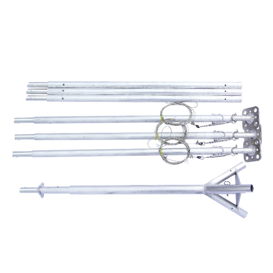
Tripod is available in 6- (standard), 7-, and 10‑segment configurations.
The mast may be suspended in the tripod hub (as pictured), or it can rest on the ground for additional load-bearing capacity. A center anchor foot is available.
Guy cables can be attached to the legs for portability and minimal installation area, or they can be staked separately.
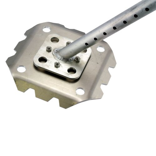
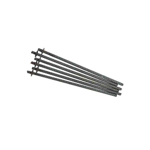
Each leg has an adjustable extension and a large foot. Holes are provided for 1/2” rebar or 3/8” screws.
Extra large feet attachments are available for installations in loose, sandy, or snowy terrain.
Specifications
| MECHANICAL – 7-SEGMENT | |
|---|---|
| Material | ¾”, 1”, and 1¼” 6061 Aluminum pipe |
| Weight | 9.8 kg (21.6 lb) |
| Functional Segment Length | 33.5 mm diameter x 0.91 m (1.3 in diameter x 3 ft) |
| Max Height* | 5.4m (17.4ft) |
| Storage/Ship Dimensions | 280 x 280 x 1070 mm ( 11 x 11 x 42 in) |
| Leg Adjustment | Pin, 25.4 mm (1 in) centers |
| Max Slope** | 13° (23%) |
| Max Base Diameter | 1.8 m (5.8 ft) |
| Max Triangular Base | Approximately 1.78 m (5.8 ft) per side |
| Leg Base | 89 mm x 89 mm (3.5 in x 3.5 in) |
| Guy Cable | 2 mm x 6.1 m (1/16 in x 20 ft) |
* Single segment in each leg position and four mast segments. (See top image.)
** One leg down hill in maximum height position. Uphill legs in storage (lowest) position.